Operation
Powering the device
Iosefka requires a 9v DC center-positive power supply. It is preferable to use a linear power supply (such as the one outlined in the BOM) instead of a switching power supply, in order to reduce noise.
The unit does not have a built-in on/off switch, so operation begins when the power supply is plugged in and ends when it is unplugged.
Plugging into an external audio source
Iosefka provides line level mono output. Simply plug a ¼" cable into Iosefka's Output Audio jack and plug the other end into your mixer or audio interface, adjusting the volume with the Volume knob as needed.
Iosefka does not have a headphone output. It is not advised to plug headphones directly into Iosefka's Output Audio Jack.
Playing Sounds
You can play sounds on Iosefka in a variety of ways. Most of these ways will be elaborated on in their own sections, but as a basic rundown:
Playing sounds with the built-in keyboard
When the Kbd Page is active (by pressing the Synth 1, Synth 2, Envelope, or LFO View switches), the 13 Key Switches play chromatic musical semitones. The lower 8 switches represent white keys and the upper 5 switches represent black keys.
Furthermore, in the Synth 1 and Synth 2 Views, the Keyboard Octave Mode is active, allowing for selecting between octave 2 through 7 of the 128 MIDI standard notes with the Data rotary encoder.
Playing sounds with the Sequencer
You can just let the synth play itself by pressing the Play/Stop switch, provided that there is an active sequencer Pattern.
More information on the Sequencer can be found in the Sequencer section of this document.
Playing sounds via MIDI
Iosefka comes with robust MIDI implementation according to the MIDI 1.0 standard. You can plug in any device that produces MIDI Note messages like a keyboard or a computer with a DAW into the MIDI Input Jack in the back of the device. Just make sure that the MIDI Channel in the Settings View matches the MIDI channel of your MIDI output device.
More information can be found in the MIDI Implementation section of this document.
Just let it drone my dude
By disabling the VCA, Iosefka becomes a drone synthesizer, so it's constantly playing sound. From the Synth 1 Layer, press the Shift Switch and turn the Mix 1 Potentiometer above the "00" value to open the VCA to enter drone mode. Turning the value to "FF" will turn drone mode to full VCA gain.
When the VCA parameter it 00, the VCA is fully closed and will only open with Envelope 3.
The OLED Display and LEDs
The combination of the OLED Display and the eight LEDs on Iosefka are meant to give thorough visual feedback on the machine's control state, known as the View (more on the View in the section below). Learning this combination is crucial to the workflow of the machine.
Most changes on the physical interface will be reflected somehow on the OLED Display. For example, when you turn a Potentiometer, a value relating to the placement of that potentiometer will change on the OLED Display. For example, turn the top left Potenetiometer and you'll see the number in the top left of the OLED Display change. Knowing that the currently lit Layer LED corresponds to the 15 numbers currently showing on the OLED Display will help you know which Parameters those numbers represent.
A detailed description of the different screens shown on the OLED Display and LEDs is provided in the View Charts section of this document.
OLED Display
A note on the use of hexadecimal
The display on Iosefka is 128x64 pixels. This plus the admittedly tiny size of the screen means that every character counts.
Because of this, most numerical values controlled by a Potentiometer are displayed in hexadecimal, a base 16 number system, instead of the standard base 10 decimal number system. This is actually how many musical trackers display numerical values as well.
Moreover, Iosefka reads the Potentiometers at 8-bit resolution, meaning the voltage from the potentiometer is read as:
- All the way down: 0 (0x00 in hexadecimal)
- All the way up: 255 (0xFF in hexadecimal)
- Halfway: 128 (0x80 in hexadecimal)
In brief, instead of counting like this:
- 0-1-2-3-4-5-6-7-8-9-10-11-12-13-14-15-16-17-18-19-20 … 251-252-253-254-255
The Parameter values count like this:
- 0-1-2-3-4-5-6-7-8-9-A-B-C-D-E-F-10-11-12-13-14 … FB-FC-FD-FE-FF
Values that are displayed in decimal
All numerical values controlled by the Data Rotary Encoder show as decimal values (...9, 10, 11...), as well as the following values on the Sequencer View: - Length - First Step - Last Step
Bipolar values
Because of the aforementioned issue with space allotted to Parameter values, adding a negative "-" symbol would break the visual convention and hog screen space. As a compromise, bipolar values are displayed as positive hexadecimal values. For example, the values for the "- Level +" Parameters for the Modulation Sources are displayed as 0 to FF, but are in reality -80 to 7F, with 0 as the center value.
To be clear (or more confusing, I don't know): - How it looks on the screen (positive hexadecimal): - Value range: 00 - FF - The center value: 80 - How it works internally: - Value range: -128 - 127 - The center value: 0
Bipolar values are mentioned in all parameters where they apply, and link back here for reference.
Hanging screens
A Hanging Screen is a screen which shows for just a few seconds, like showing the Mode when a View is changed, or any time the Data rotary encoder is turned. To view this screen for longer, hold down the Data rotary encoder switch by pressing down on the shaft. The Hanging Screen will persist for as long as the screen is held (plus a few seconds).
Display Off Timer
To maintain the longevity of the OLED Display, it will automatically turn off after 5 minutes if none of the physical components are changed (like turning a Potentiometer), or if the sequencer is not running, or if there are no incoming MIDI messages.
LEDs
As mentioned above, the Layer LEDs and Page LEDs give visual feedback to the respective Layer and Page in the device's current View, described below.
The View
The total state of the physical user interface is called the View. The View consists of three physical sections:
- Pages - The functions of the 13 Key switches on the control board
- Layers - The Parameters controlled by the 15 Potentiometers on the control board
- Modes - The data selectable by the single Data rotary encoder on the control board
Therefore, the View is determined by which state the Page, Layer, and Mode is currently set on the device. The OLED Display as well as the Layer LEDs and Page LEDs give visual feedback on which View is currently active.
Changing the View
The View can be changed with the five View switches on the bottom left of the control board.
To see a list of all the Views, visit the View Charts section of this document.
Page
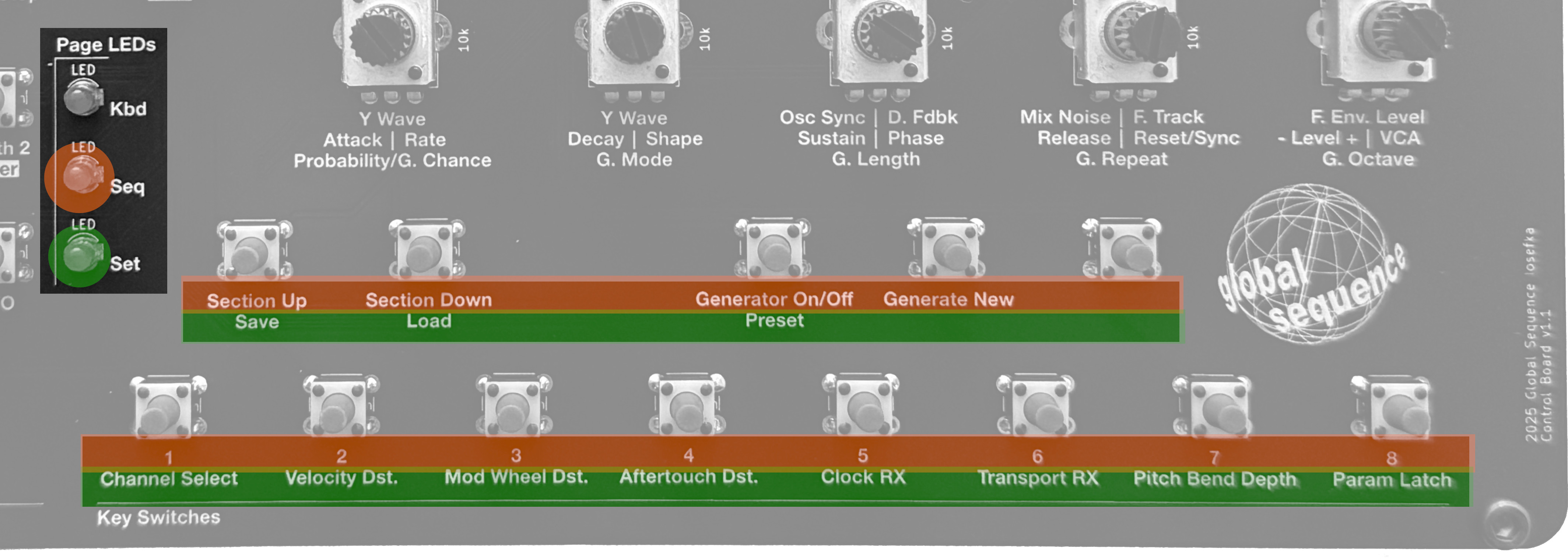
The function performed by each of the 13 Key switches is determined by which Page is currently active. The currently lit Page LED indicates the current page, and the function of that specific Key Switch is either:
- Key Page - A musical semitone in the layout of a standard piano keyboard
- Seq Page - The first line of text beneath the Key switch
- Set Page - the second line of text beneath the Key switch
The image below illustrates how the Page LEDs indicate what each switch does. The orange sections indicate Sequencer functions and the green indicates Settings functions.
To see a list of all the Pages and their corresponding Key switch functions, visit the Page Switch Function Chart section of this document.
Layer
Before delving into the Layer explanation, a definition: A Parameter in the context of this document is any value that is changeable with a Potentiometer.
The Layer is the state which determines which parameter is controlled by one of the fifteen Potentiometers on Iosefka's control board. The Layers are arranged in a way that represents aspects of the synthesizer from a big-picture perspective. For example, the Synth 1 Layer contains the parameters for the oscillators, mixer and filter, while the Synth 2 Layer contains additional synthesizer effects (with a few parameters that are shared with Layer 1). All parameters on the Envelope and LFO Layers are dedicated to those respective Modulation Sources.
The Layer LED that is currently lit indicates which Parameter name beneath the Potentiometer is currently active. To elaborate, in the image below, note the corresponding color over the Layer LEDs to the Parameter name beneath the Potentiometer. This applies to every Parameter beneath the Potentiometers on the control board e.g. top left Layer LED (Indicating Synth 1 Layer) = top left Parameter, etc.
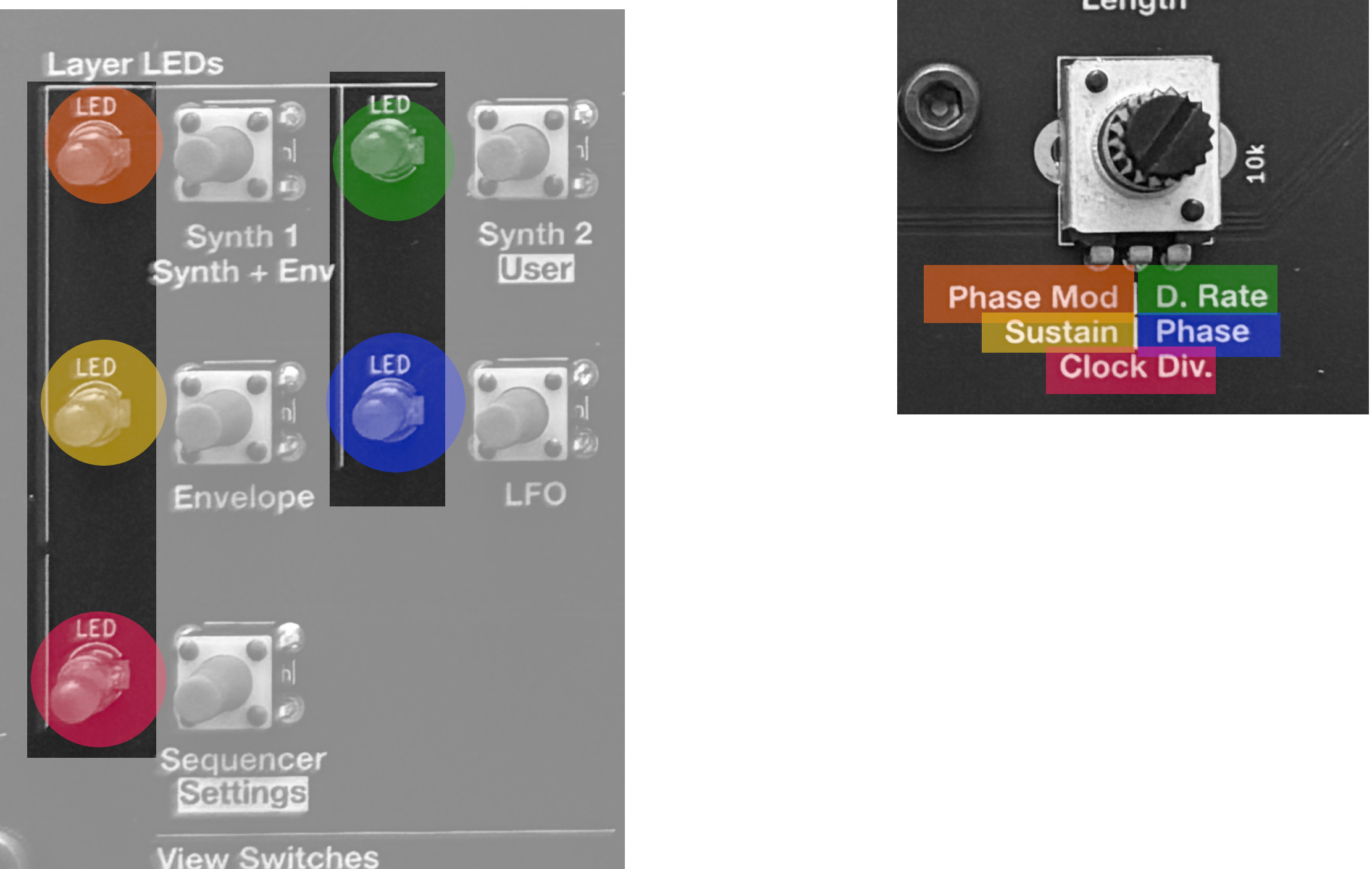
Note: If only one Parameter name appears in a row beneath the Potentiometer, that means that Parameter is active for either layer in that row. For example in the below image, the parameter "Cutoff" is in effect when the active Layer is either Synth 1 or Synth 2.
To see a list of all the Layers and their corresponding Potentiometer Parameters, visit the Layer Parameter Control Chart section of this document.
Mode
The Data rotary encoder is responsible for handling the input of specific data values depending on which Page or Layer is currently active, as well as several other contexts. The state which determines the data being handled by the Data rotary encoder is called the Mode.
The Mode controls things like the octave of the notes played on the keyboard, the modulation destination of all Modulators, the BPM of the Sequencer, etc.
On all Views except for the Settings View, the current Mode can be viewed in a few different ways:
- Pressing down on the Data rotary encoder shaft to actuate the switch
- Switching the View
- Turning the Data rotary encoder
To see a list of all the Modes, their contexts, and how to view them, visit the Mode Encoder Data List section of this document.